Getting Started
🏊 Smart Swimming Pool: Home automation for smarter control of your swimming pool
WARNING: 230V Mains Voltage
This project operates with 230V AC mains voltage and should only be built by individuals with basic electronics knowledge. Always use an RCD (residual-current device). This project is not CE/UL certified and not intended for commercial use.
Example Environment
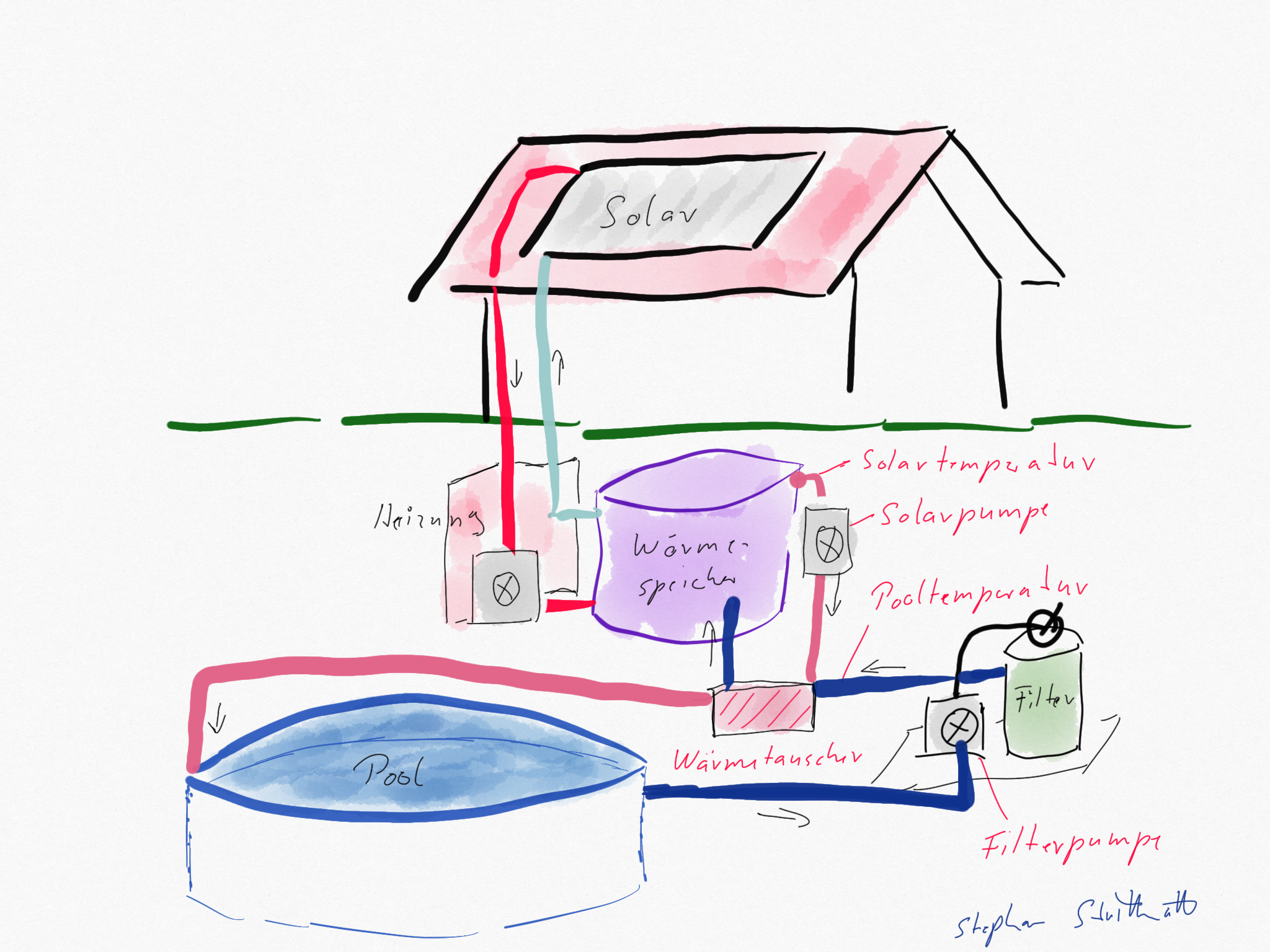
In a typical setup, a thermal solar system heats water and supports the home heating system. The heated water is stored in a buffer tank, which has a third circulation loop for the pool. A pump attached to this loop circulates pool water through a heat exchanger:
Basic Requirements
- Swimming pool with sand filter system
- Heating circuit with a pump-switchable heat exchanger
- Solar heat storage tank with an additional heating circuit for the pool
Parts List (Bill of Materials)
| Component | Est. Price | Notes |
|---|---|---|
| ESP32 DevKit V1 | 10–15 € | At least 4MB flash, USB cable included |
| DS18B20 temperature sensor (2x, waterproof) | 8–12 € | Stainless steel probe, 1m cable |
| 2-Channel Relay Module (Dual relay) | 5–8 € | Standard active-low module — see notes |
| 4.7kΩ resistors (2x) | < 1 € | Pull-up resistors for OneWire bus |
| Breadboard + jumper wires | 3–8 € | For prototyping; use perfboard for permanent build |
| USB power supply (5V / 1A+) | 5–10 € | For ESP32 + relay module |
| Enclosure (IP54+) | 5–10 € | Optional but recommended for outdoor use |
| Total | ~45–75 € | Excluding pool pump / heat exchanger infrastructure |
⚠️ Relay module note: The firmware drives relays active-low (GPIO LOW = relay ON, GPIO HIGH = relay OFF). This matches the vast majority of cheap 2-channel 5V relay modules. During ESP32 boot, GPIOs are briefly in high-impedance state — the firmware sets them HIGH (relay OFF) as soon as possible after startup. If your module behaves differently (active-high), see the FAQ for configuration options.
Hardware Assembly
Breadboard Layout
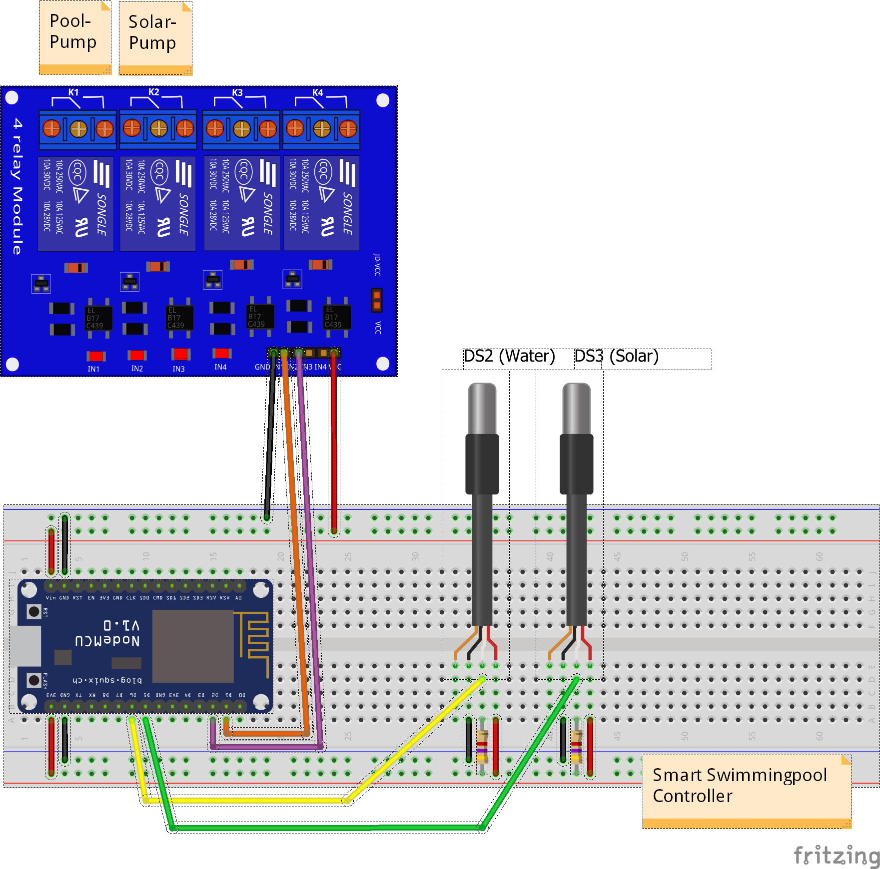
The ESP32 and relay module on a breadboard — the simplest way to get started.
Step 1: Prepare the ESP32
- Connect the ESP32 to your computer via USB.
- Verify it appears as a serial port (
/dev/ttyUSB0on Linux,COM3on Windows). - Install CP210x or CH340 drivers if needed (CP210x drivers, CH340 drivers).
Step 2: Connect the Temperature Sensors
The DS18B20 sensors use the OneWire protocol. Connect them as follows:
The firmware (esp32dev environment) assigns each sensor its own GPIO pin:
| Sensor | ESP32 Pin | Wire Color (typical) |
|---|---|---|
| Solar collector (DS18B20 #1) | GPIO32 | VDD=Red, GND=Black, DATA=Yellow/White |
| Pool water (DS18B20 #2) | GPIO33 | VDD=Red, GND=Black, DATA=Yellow/White |
Important: Connect a 4.7kΩ resistor between each DATA line and 3.3V (pull-up). OneWire requires a separate pull-up per GPIO pin. For two sensors on separate GPIOs, you need two 4.7kΩ resistors.
Step 3: Connect the Relay Module
| ESP32 Pin | Relay Module | Notes |
|---|---|---|
| GPIO26 | Relay IN1 | Heating circuit pump |
| GPIO25 | Relay IN2 | Circulation/filter pump |
| 5V (VIN) | Relay VCC | 5V not 3.3V! |
| GND | Relay GND | Common ground with ESP32 |
⚠️ Power: The relay module requires 5V power (use the ESP32’s VIN pin when powered via USB). Do not power it from the 3.3V pin. Connect the ESP32 GND to the relay module GND (common ground).
Step 4: Final Checks
Before connecting any pump or mains voltage, follow the Commissioning Checklist — a complete step-by-step guide covering hardware check, firmware test, sensor verification, relay test, and automation check.
Key points before proceeding:
- Double-check all connections against the schematic.
- Verify the relay module: with the ESP32 powered and NOT yet controlling the relays, measure the GPIO pins with a multimeter — they should be HIGH (relay OFF). After toggling a relay in the web interface, the corresponding GPIO should go LOW (relay ON).
- Flash the firmware first (see below) and test with the web interface without connecting pumps.
- Still no 230V mains? Only connect pump/valve wiring after successful firmware tests.
Firmware Installation
PlatformIO (Recommended)
⚠️ Important: The pool-controller is a PlatformIO project. It does not have an Arduino IDE
.inofile. PlatformIO is the only supported build method.
- Install Visual Studio Code and the PlatformIO extension.
- Clone the repository:
git clone https://github.com/smart-swimmingpool/pool-controller.git cd pool-controller - Open the folder in VS Code — PlatformIO will auto-detect the project.
- Select the correct environment: The project has a default environment for the NORVI AE01-R industrial controller. For a standard ESP32 DevKit, switch to the
esp32devenvironment:- Click the PlatformIO logo in the VS Code footer bar (⚡ icon)
- Go to Project Tasks → esp32dev
- Or use the environment switcher at the bottom of the VS Code window
- Connect the ESP32 via USB.
- Step A — Upload the firmware: Click the → (Upload and Monitor) button next to
esp32devin the PlatformIO footer bar. The firmware will compile and flash. - Step B — Upload the filesystem (web interface): The web UI is stored in a separate LittleFS partition and must be uploaded after the firmware:
- In VS Code, open the PlatformIO tab → esp32dev → Platform → Upload Filesystem Image
- Or run from the terminal:
pio run -e esp32dev -t uploadfs - Without this step, the web interface will show a missing assets fallback page instead of the configuration UI.
Verify the Flash
After flashing, open the serial monitor (115200 baud). You should see:
[INFO] Pool Controller v3.3.0 starting...
[INFO] WiFi: Starting in AP mode
[INFO] AP: 'Pool-Controller-Setup'. IP: 192.168.4.1
The ESP32 starts in Access Point (AP) mode by default.
First Run & Configuration
Step 1: Connect to the ESP32
- Scan for WiFi networks — you’ll see
Pool-Controller-Setup(open network, no password). - Connect to it from your phone or laptop.
- Open a browser and go to http://192.168.4.1
Step 2: Configure WiFi
- The web interface shows a configuration page.
- Enter your home WiFi SSID and password.
- Click Save — the ESP32 will reboot and connect to your network.
Step 3: Set up MQTT
- Find the ESP32’s IP address on your router or from the serial monitor.
- Open
http://<esp32-ip>/in your browser. - Go to Configuration → MQTT.
- Enter your MQTT broker address (e.g.,
192.168.1.100orcore-mosquitto). - If using authentication, enter username/password.
- Click Save — the controller will reconnect to MQTT.
No MQTT broker yet? Install Mosquitto on any machine on your network, or use the Mosquitto add-on in Home Assistant.
Step 4: Home Assistant Integration
If you use Home Assistant with MQTT configured:
- The controller automatically publishes MQTT discovery messages.
- In Home Assistant, go to Settings → Devices & Services.
- Click Add Integration → MQTT (if not already configured).
- The pool controller should appear as a new device automatically.
- All sensors, controls, and configuration parameters appear as entities — no manual setup needed.
▶️ Detailed guide: See the Home Assistant Integration Guide for the complete entity reference, dashboard setup, automation examples, and troubleshooting.
Step 5: Connect the Pumps
Only now — after verifying everything works:
- Disconnect the ESP32 from USB power.
- Wire the relay outputs to your pump contactors/valves.
- Use appropriate cable cross-sections for 230V wiring.
- Connect mains power through an RCD (FI-Schutzschalter).
- Power the ESP32 via its USB supply (keep it isolated from mains).
WARNING: 230V Mains Voltage
This project operates with 230V AC mains voltage and should only be built by individuals with basic electronics knowledge. Always use an RCD (residual-current device). This project is not CE/UL certified and not intended for commercial use.
Modular System Overview
The Getting Started guide focuses on the Pool Controller, which is the central module. The system has additional optional modules:
| Module | Purpose | When to Add |
|---|---|---|
| Pool Controller (this guide) | Main control: pumps, heating, circulation | Required — start here |
| Home Assistant | Native MQTT Discovery integration | Automatic — no setup needed |
| Pool Monitor | Solar-powered wireless temperature display | After controller is running |
| Grafana Dashboard | Data visualization and history | When you want historical charts |
| openHAB Configuration | Integration with openHAB smart home | If you use openHAB instead of Home Assistant |
| Smart Analyzer (planned) | Water quality monitoring | Not yet available |
What’s Next?
Once your Pool Controller is running:
- Explore the Home Assistant Integration Guide for the complete entity reference, dashboard setup, and automation examples
- Set up the Grafana Dashboard to visualize temperature trends
- Add the Pool Monitor for a dedicated display
- Check the FAQ if you run into issues
- Follow the openHAB Integration Guide to set up openHAB step by step
- Reference the openHAB Configuration for the complete openHAB config files
Preparations
If a heating circuit with a heat exchanger is in place, you can start implementing the smart pool control.
The heart of the system is the Pool Controller. It handles:
- Circulation scheduling for sand filter cleaning
- Switching on the heating circuit to warm the pool water
- Reporting status and temperature data for integration with Smart Home servers
The Pool Controller uses Home Assistant MQTT discovery for seamless smart home integration. With the configuration presented here, the pool controller can be quickly set up and controlled from any Home Assistant-compatible app.
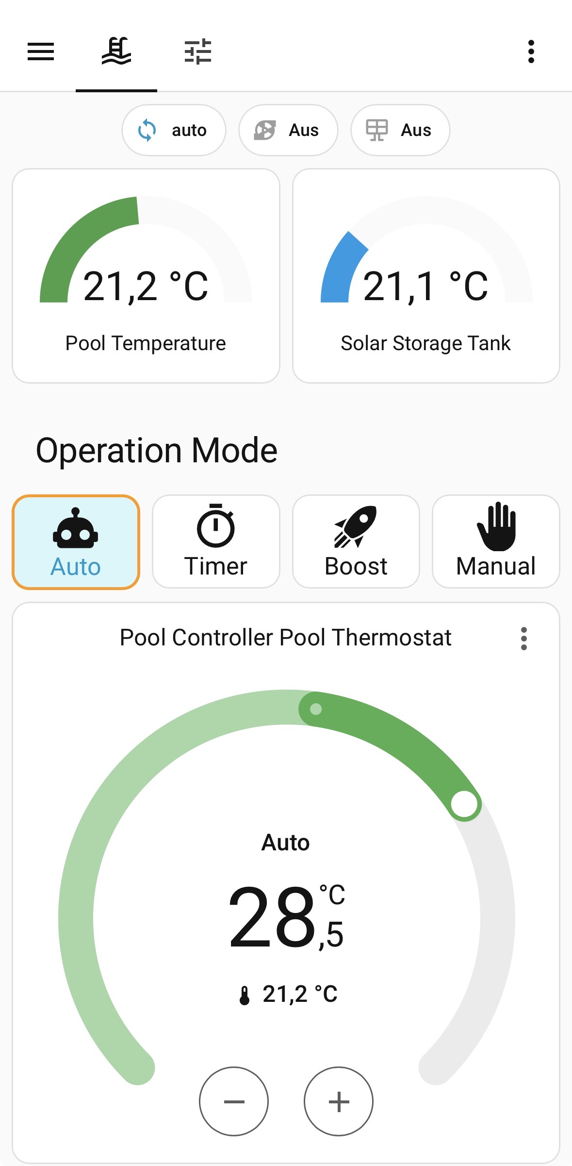
Home Assistant Dashboard
The pool controller automatically registers all sensors and controls in Home Assistant via MQTT discovery. Below is an example of the dashboard and the corresponding configuration entries:
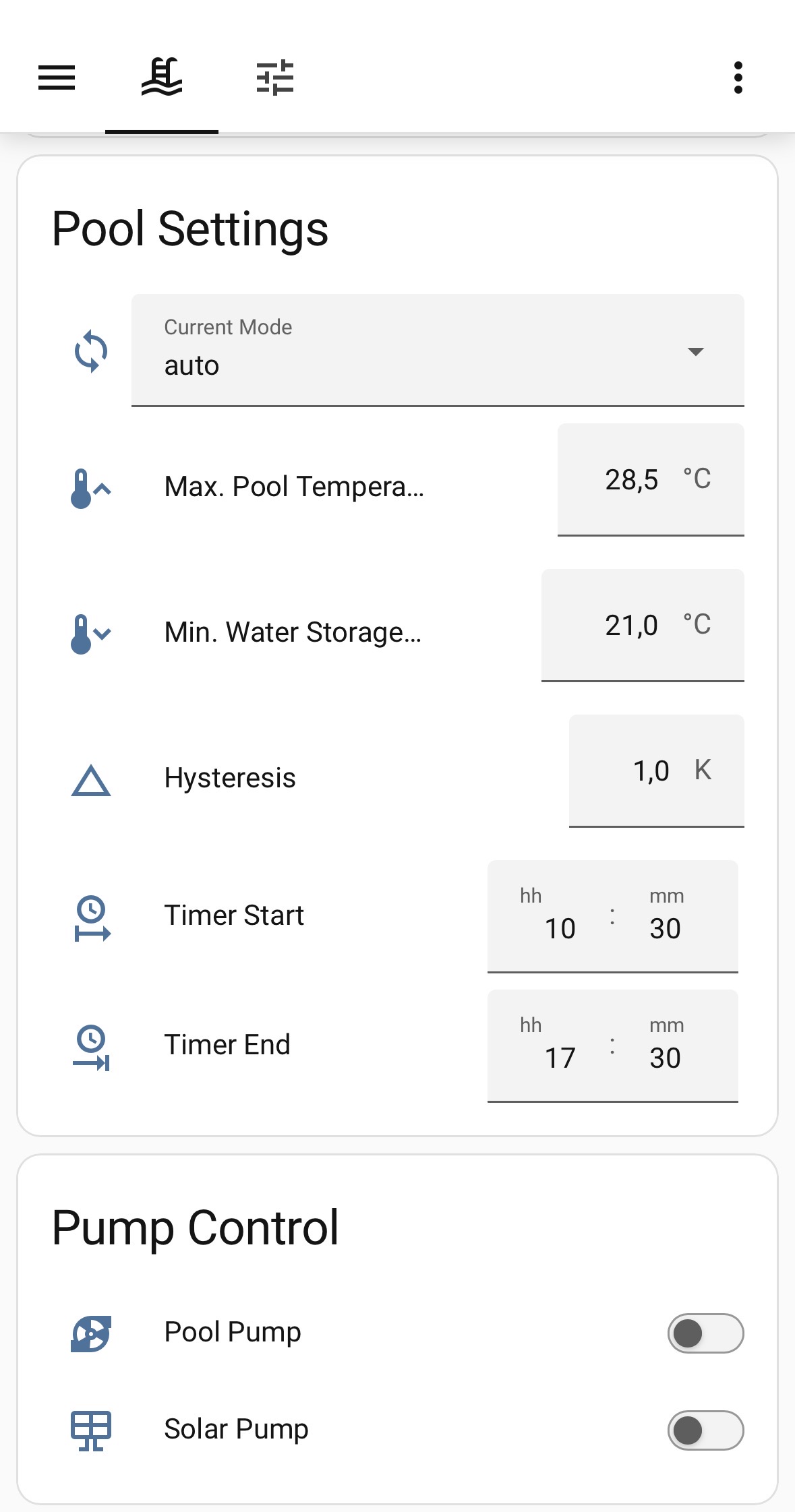
Pool Controller entities shown in the Home Assistant dashboard
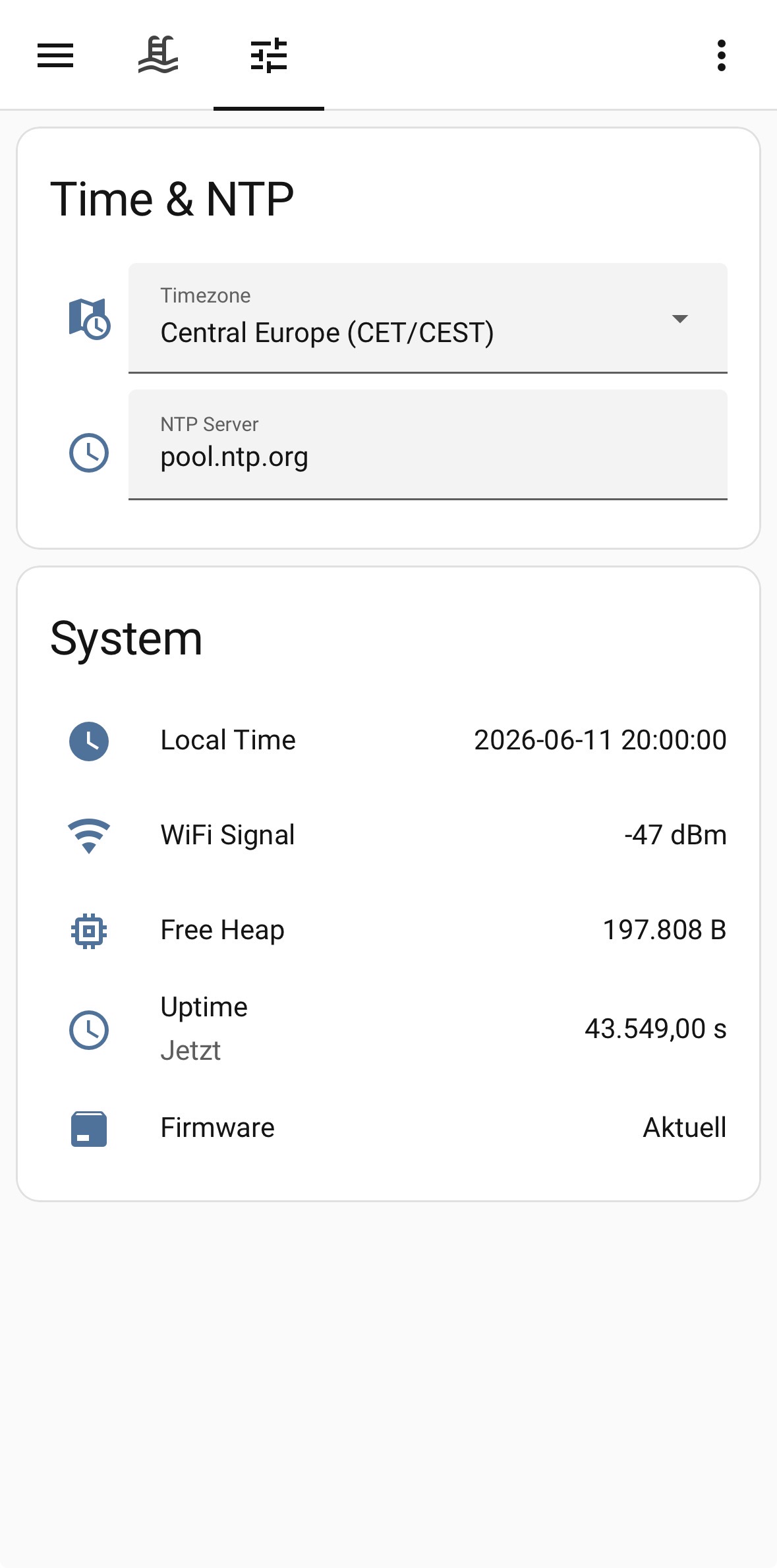
MQTT discovery device entry with all sensors and controls
Configuration entries for the pool controller in Home Assistant
History
🏊 Smart Swimming Pool originated from an earlier project that was not yet modular and had all control logic implemented as openHAB rules.
The first version ran in Summer 2018 and revealed several weaknesses:
- Controlling pumps via 433 MHz socket switches was unreliable — no feedback meant the actual state was unknown
- Switching logic lived in openHAB rules, causing problems when WiFi was unreliable
- MQTT messages used a proprietary format
Based on these lessons, the revised 🏊 Smart Swimming Pool was built: modular, resilient, and standards-based.