Hardware Guide
Overview
This guide walks you through building the Pool Controller hardware — from selecting parts to final assembly. Even if you’ve never soldered before, the step-by-step instructions will help you get it right.
Target audience: DIY electronics enthusiasts with basic soldering experience. Total cost: under 100€ (excluding pumps and pool infrastructure).
Safety First ⚠️
- The controller switches 230V AC mains voltage to the pumps. Improper wiring poses risk of electric shock or fire.
- Only work on the circuit when disconnected from power.
- Use a residual-current device (RCD) for the pump circuit.
- Keep sensor wiring (low voltage) physically separate from mains wiring.
- If in doubt, consult a qualified electrician for the mains connection.
Required Parts (BOM)
| # | Component | Qty | Approx. Cost | Notes |
|---|---|---|---|---|
| 1 | ESP32 Development Board (e.g. ESP32 DevKit V1, NodeMCU-32S) | 1 | 10–15€ | Ensure it has at least 4MB flash |
| 2 | DS18B20 Temperature Sensor (waterproof, stainless steel probe, 1m cable) | 2 | 8–12€ | One for pool water, one for solar collector |
| 3 | 2-Channel 5V Relay Module (with optocoupler isolation) | 1 | 5–8€ | Must be active-high (see notes below) |
| 4 | Resistor 4.7kΩ (¼W or ⅛W, metal film or carbon film) | 2 | < 1€ | Pull-up for the OneWire data lines |
| 5 | Breadboard + jumper wires (for prototyping) OR Perfboard + pin headers/screw terminals (for permanent build) | 1 | 3–8€ | |
| 6 | USB power supply 5V/≥1A (e.g. phone charger) | 1 | 5–10€ | For the ESP32 alone |
| 7 | Hookup wire, 0.14–0.5mm² (AWG 26–20), various colors | — | 3–5€ | |
| 8 | Optional: enclosure (ABS/PVC project box, IP54 or better) | 1 | 5–10€ | Protect from splashes/dust |
| 9 | Optional: screw terminals (2-pin, 5mm pitch) | 4–6 | 2–3€ | For removable sensor/power connections |
| 10 | Optional: DS3231 RTC module | 1 | 3–5€ | Backup timekeeping (not required for normal NTP operation) |
| Total | ~45–75€ | Without enclosure; well under 100€ |
Where to Buy
All parts are widely available on Amazon, AliExpress, eBay, or at electronics distributors like Reichelt, Pollin, Conrad (DE/AT/CH).
- ESP32: Search for “ESP32 DevKit V1” or “ESP32 NodeMCU-32S”. Avoid ESP32-S2/S3/C3 variants unless you adapt the firmware — the project targets standard ESP32 (Xtensa dual-core).
- DS18B20: Look for stainless steel, waterproof probes with 1m cable. Cheaper plastic-encapsulated sensors work too but are less durable outdoors.
- Relay Module: Read the module specification carefully. The firmware uses active-high logic (GPIO HIGH → relay ON). Many cheap modules are active-low with a jumper to switch. Check the documentation or use a jumper wire to verify before wiring permanently.
- Resistors: Any 4.7kΩ ±5% resistor works. Buy a 100-pack for < 3€.
Pin Assignment (Firmware Defaults)
The firmware uses an optimized pin assignment that avoids strapping pins and
ADC2-related issues (see Alternative Pin Assignment
for details). Defined in src/Config.hpp:
| Constant | GPIO | Purpose |
|---|---|---|
PIN_DS_SOLAR | GPIO32 | DS18B20 data — Solar collector temperature |
PIN_DS_POOL | GPIO33 | DS18B20 data — Pool water temperature |
PIN_RELAY_POOL | GPIO25 | Relay control — Pool circulation pump |
PIN_RELAY_SOLAR | GPIO26 | Relay control — Solar heating pump |
PIN_LED_STATUS | Built-in LED | Status LED (Homie convention blink codes) |
Note: These pins are chosen for maximum compatibility. GPIO15/16/18/19 (the original assignment) work for most users, but the optimized pins eliminate any boot-strapping risk and avoid ADC2 pins entirely — see Alternative Pin Assignment for the original layout.
Wiring Diagram
 ─── POWER SUPPLY ──────────────────────────────────────────────────

  [USB PSU 5V/1A+]           [ESP32 Board]           [Relay Module]
   ┌──────────┐              ┌─────────────┐          ┌────────────┐
   │ 5V (+) ──┼──────────────┤ VIN         │          │ VCC        │
   │          │              │  (powers    │      ┌───┤ (powers    │
   │          │              │   board)    │      │   │  coils)    │
   │          │              │             │      │   │            │
   │          │              │ 3V3 ───┬────┘      │   │ GND ◄──────┼──┐
   │          │              │        │           │   └────────────┘  │
   │ GND ─────┼──────────────┤ GND ◄──┼───────────┼──────────────────┘
   └──────────┘              └────────┘           │

 ─── SENSORS ──────────────────────────────────────────────────────

  [DS18B20 Solar]                               [DS18B20 Pool]
   ┌───────────┐                                 ┌───────────┐
   │ VDD (red) ─┼── 3.3V ─────────────────────────┼── VDD (red)│
   │           │                                 │           │
   │ GND (blk) ─┼── GND ──────────────────────────┼── GND (blk)│
   │           │                                 │           │
   │DATA (yel) ─┼── GPIO32 (PIN_DS_SOLAR)         │           │
   │           │  │                              │           │
   │           │  └──[4.7kΩ]── 3.3V ← pull-up    │           │
   │           │                   resistor      │           │
   │           │                                 │DATA (yel) ─┼── GPIO33 (PIN_DS_POOL)
   │           │                                 │           │  │
   │           │                                 │           │  └──[4.7kΩ]── 3.3V
   └───────────┘                                 └───────────┘

 ─── RELAY CONTROL SIGNALS ────────────────────────────────────────

  ESP32 GPIO25 ────────────────────────────────── Relay IN1 (Pool)
  ESP32 GPIO26 ────────────────────────────────── Relay IN2 (Solar)

 ─── STATUS INDICATION ────────────────────────────────────────────

  ESP32 Built-in LED (GPIO2) ── Status blink codes (Homie)

 ─── RELAY LOAD SIDE (230V AC) ────────────────────────────────────

  L (mains) ─── RCD ─── MCB ──┬── Relay COM1 ── Pool Pump
                               └── Relay COM2 ── Solar Pump
  N (neutral) ───────────────────────── Neutral bar ── Pump N
Wire Connections (Step by Step)
1. Temperature Sensors (DS18B20)
The DS18B20 has three wires (on waterproof probes: typically red = VDD, yellow/white = DATA, black = GND — but verify with your sensor’s datasheet):
| DS18B20 Wire | Color (typical) | Connect to |
|---|---|---|
| VDD | Red | ESP32 3.3V |
| GND | Black | ESP32 GND |
| DATA | Yellow / White | ESP32 GPIO32 (solar) or GPIO33 (pool) |
Critical — add the 4.7kΩ pull-up resistor:
Each sensor DATA line must have a 4.7kΩ resistor connecting it to 3.3V. Without it, the sensor will not be detected.
   Solar DATA ──── 4.7kΩ ──── 3.3V
   Pool  DATA ──── 4.7kΩ ──── 3.3V
Solder the resistor as close to the ESP32 pin header as possible, connecting between the DATA pin and the 3.3V rail. The resistor can be any 4.7kΩ ±5% (¼W or ⅛W, metal film or carbon film).
2. Relay Module
| Relay Terminal | Typical Label | Connect to | Wire Color |
|---|---|---|---|
| Module power | VCC or VDD | 5V (from ESP32 VIN or external 5V PSU) | Red |
| Ground | GND | GND (common ground with ESP32) | Black |
| Control input 1 | IN1 or D1 | GPIO25 (Pool Pump) | Yellow/Blue |
| Control input 2 | IN2 or D2 | GPIO26 (Solar Pump) | Green/Blue |
Important — Logic Level: The firmware sets the GPIO pin HIGH (3.3V) to activate (close) the relay. If your relay module switches with LOW instead (active-low), look for a jumper on the module to change the mode, or choose a different module — active-high modules are easier to work with.
Load wiring (230V side):
   L (mains live) ─── RCD ─── MCB ──┬── Relay COM1 ── Pool Pump
                                     │       NO1 ─────┘
                                     │
                                     └── Relay COM2 ── Solar Pump
                                             NO2 ─────┘
N (neutral) ───────────────────────── Neutral bar ── Pump N- Connect the pump’s live wire to the relay’s COM (common) terminal.
- Connect the relay’s NO (normally open) terminal to the pump.
- The other pump wire goes to neutral (N).
- Always wire the 230V circuit through an RCD and appropriately rated MCB.
3. Power Supply
| Component | Voltage | Source | Notes |
|---|---|---|---|
| ESP32 board | 5V | USB charger port (on ESP32) | Powers the board + provides 5V on VIN pin |
| Relay module coils | 5V | ESP32 VIN pin (same as USB input) | The relay module draws power from the same 5V supply |
| DS18B20 sensors | 3.3V | ESP32 3V3 output pin | Both sensors share the same 3.3V rail |
| (Optional) RTC DS3231 | 3.3V | ESP32 3V3 output pin | Same rail as sensors |
Important: The ESP32’s on-board 3.3V regulator can supply ~600mA. The DS18B20 sensors draw < 5mA total — well within limits. If you add many additional 3.3V components, consider an external 3.3V regulator.
Step-by-Step Assembly
Prototyping on a Breadboard
- Place the ESP32 on the breadboard straddling the center gap
- Connect power rails: 3.3V and GND rails on both sides
- Insert the 4.7kΩ resistors: Between the DATA row and 3.3V rail
- Connect DS18B20 sensors: Use jumper wires for VDD (3.3V), GND, and DATA
- Connect the relay module: Jumper wires for VCC (5V), GND, IN1, IN2
- Power via USB: The ESP32’s VIN/USB pin provides 5V for the relay module
- Double-check all connections before applying power
- Verify: See First Power-On below
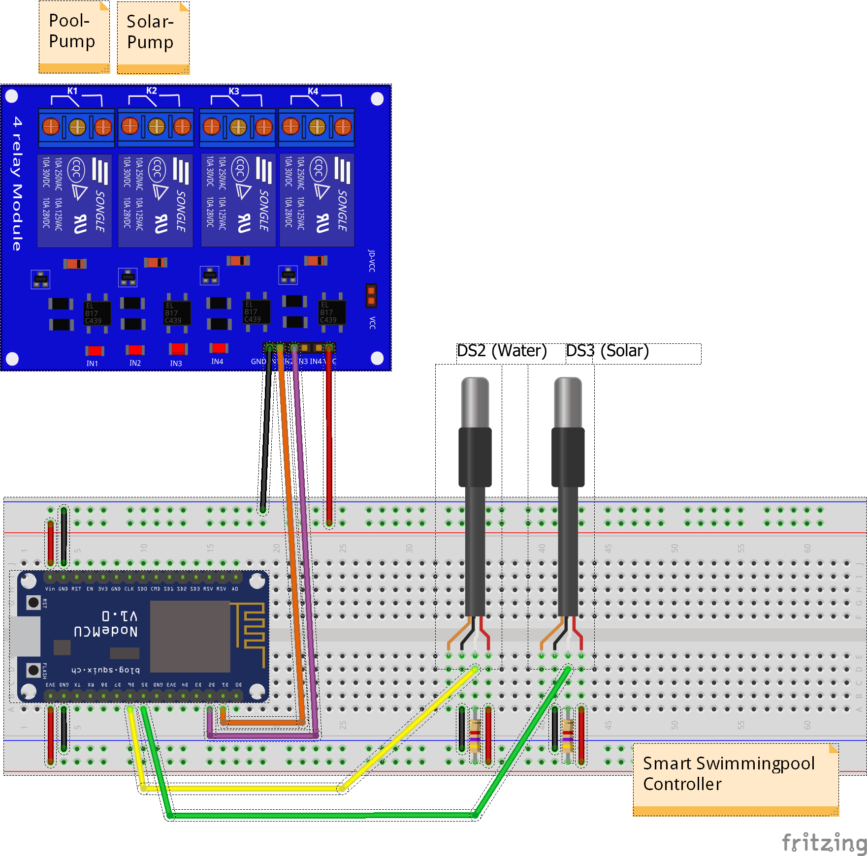
Breadboard prototype with ESP32, DS18B20 sensors, 4.7kΩ pull-up resistors, and 2-channel relay module
💡 Tip: Use different colored jumper wires for clarity — e.g., red for power (3.3V/5V), black for GND, yellow for sensor data, blue for relay control.
Permanent Assembly on Perfboard
Once you’ve verified the circuit on a breadboard, build the permanent version:
- Plan the layout: Arrange components on the perfboard before soldering. Keep the 230V relay terminals at one edge, sensors at the opposite edge.
- Solder in this order:
- Pin headers / screw terminals for the ESP32 (socket it, don’t solder directly)
- Resistors (4.7kΩ)
- Pin headers for the relay module (socket it too)
- Screw terminals for sensor connections
- Wire routing: Use solid core wire for connections. Keep data lines short.
- Inspect for solder bridges: Check each joint with a magnifier or multimeter (continuity test).
- Mount in enclosure: Use standoffs or double-sided foam tape. Drill holes for sensor and relay cable entries. Use cable glands (PG7/PG9) for a water-resistant seal.
Manufacturing Tips
Soldering
- Use leaded solder (Sn60Pb40 or Sn63Pb37) for easiest handling — it flows better than lead-free, especially for beginners.
- Flux: Use rosin-core solder; add liquid flux for stubborn joints.
- Temperature: Set iron to 320–350°C for leaded, 370–400°C for lead-free.
- Iron tip: Clean with a wet sponge or brass wool before every joint.
- Good joint: Shiny, concave fillet that flows around the component lead. A dull, cracked, or ball-shaped joint is bad — reheat and add fresh solder.
Enclosure
- Choose an ABS or PVC project box with at least IP54 rating for outdoor installation (splash protection).
- Drill ventilation holes if the relay module gets warm, but angle them downwards to reduce water ingress.
- Mount the ESP32 on M2.5 or M3 nylon standoffs to avoid short circuits.
- Label external connectors (pool sensor, solar sensor, pump 1, pump 2, USB power).
- Use cable glands (PG7 for thin sensor cables, PG9 for thicker power cables) where wires enter the enclosure.
Cable Management
- Label both ends of each wire with heat-shrink wrap or small adhesive labels — future-you will thank past-you.
- Keep sensor and relay wires separate inside the enclosure to minimize electrical noise coupling.
- Strain relief: Tie internal wires to mounting posts or use cable ties so that pulling on external cables doesn’t stress solder joints.
- Service loop: Leave enough slack inside the enclosure so you can open it and work without disconnecting everything.
Outdoor Sensor Installation
- DS18B20 probes are waterproof but the cable entry at the sensor end is not always fully sealed. Apply heat-shrink tubing over the cable joint or use self-amalgamating silicone tape for outdoor installations.
- Route sensor cables in conduit (PVC or flexible) where they are exposed to mechanical stress (lawn, pavement).
- Max cable length: DS18B20 works reliably up to ~30m with a 4.7kΩ pull-up and twisted-pair cable. For longer runs, reduce the pull-up to 2.2kΩ or use a dedicated OneWire driver.
- Position the pool sensor in the pump circuit (after the filter, before the pump return) for accurate average pool temperature.
- Position the solar sensor at the hottest point of the solar collector (usually the top outlet pipe).
Power Supply Options
| Option | Pros | Cons |
|---|---|---|
| USB phone charger (5V/1A+) | Cheap, readily available, safe | Limited current for additional peripherals |
| DIN-rail PSU (Mean Well HDR-15-5 or similar) | Professional, reliable, fits in electrical cabinet | Slightly more expensive (~15€) |
| ESP32 VIN from USB + relay from same 5V | Simple wiring | Total current must stay under ESP32 board’s limit |
Recommendation: If you’re installing in a permanent location near your pump control panel, use a DIN-rail 5V PSU (e.g., Mean Well HDR-15-5). It’s clean, reliable, and can power both the ESP32 and the relay module without issue.
Alternative — Industrial controller: The NORVI IIOT-AE01-R is an ESP32-based industrial controller with built-in relays, 24V DC supply, DIN-rail mount, and CE certification. If you already have a 230V AC → 24V DC power supply, no additional 5V PSU is needed. See the NORVI AE01-R Configuration Guide for details.
First Power-On and Testing
1. Visual Inspection
Before connecting power:
- Check for solder bridges between adjacent pins
- Verify polarity of all components (DS18B20 VDD/GND, relay VCC/GND)
- Ensure no stray wire strands are shorting neighboring pins
- Measure resistance between 3.3V and GND — should be > 10kΩ (not shorted)
2. Power On
- Connect USB power (or 5V PSU)
- The ESP32’s built-in LED follows the LED Status Codes:
- Fast blink (5 Hz) — AP mode (no WiFi configured welcome page active)
- Slow blink (1 Hz) — WiFi connecting
- Mostly on, brief blink every 2s — WiFi connected, MQTT disconnected
- Solid on — WiFi + MQTT fully connected
3. Verify Sensors
Open the serial monitor (115200 baud):
Pool Controller v3.3.0
Starting up...
✓ Pin configuration validated - no conflicts (optimierte Belegung)
  Solar Temp (DS18B20): GPIO32
  Pool Temp  (DS18B20): GPIO33
  Pool Pump  (Relay):   GPIO25
  Solar Pump (Relay):   GPIO26
  Status LED:           GPIO2 (LED_BUILTIN)
If sensors are connected and working:
Solar temperature: 25.3°C
Pool temperature:  22.1°C
If you see Sensor error or -127°C, check:
- 4.7kΩ pull-up resistor present on each DATA line?
- DS18B20 VDD connected to 3.3V (not 5V)?
- DS18B20 GND connected to common ground?
- DATA pin matches the firmware configuration?
4. Test Relays
From the Web UI (Configuration tab) or via serial command:
Mode: manual
Pool pump: ON  → relay should click, pump starts
Solar pump: ON → relay should click, pump starts
If relay doesn’t click:
- Is the relay module powered (5V between VCC and GND)?
- Is the logic level correct (active-high vs active-low)?
- Does the LED on the relay module light up when GPIO goes HIGH?
Troubleshooting
| Symptom | Likely Cause | Fix |
|---|---|---|
“Sensor error” or -127°C | Missing pull-up resistor | Add 4.7kΩ between DATA and 3.3V |
| “Sensor error” | Wrong GPIO pin | Check PIN_DS_SOLAR/PIN_DS_POOL in src/Config.hpp |
| Intermittent sensor readings | Loose connection or noise | Check solder joints, separate data from relay wires |
| Relay doesn’t activate | Wrong logic level | Check active-high vs active-low; add jumper or change firmware |
| Relay clicks but pump doesn’t run | 230V wiring issue | Check COM/NO terminals, verify pump connection |
| ESP32 won’t boot (brownout) | Insufficient power | Use 5V/≥1A power supply; add 100µF capacitor near VIN |
| ESP32 resets when relay switches | Voltage spike on relay coil | Add flyback diode across relay coil, or use module with built-in protection |
| Sensor readings jump when relay switches | Electrical noise | Route sensor wires away from relay/power wires |
Alternative Pin Assignment (Original)
The firmware now uses the optimized pins (GPIO32/33/25/26) by default,
as shown in the Pin Assignment table above.
The original assignment (GPIO15/16/18/19) is available if you need to share pins
with legacy shield boards or other hardware — simply edit src/Config.hpp:
constexpr uint8_t PIN_DS_SOLAR{15};     // was 32
constexpr uint8_t PIN_DS_POOL{16};      // was 33
constexpr uint8_t PIN_RELAY_POOL{18};   // was 25
constexpr uint8_t PIN_RELAY_SOLAR{19};  // was 26
| Function | Optimized (Default) | Original Pin | Why the change? |
|---|---|---|---|
| DS18B20 Solar | GPIO32 | GPIO15 | GPIO15 is a Strapping pin — removing OneWire eliminates any boot risk |
| DS18B20 Pool | GPIO33 | GPIO16 | Clean separation from remaining Strapping pin GPIO0 |
| Relay Pool | GPIO25 | GPIO18 | Avoid ADC2 pins (18/19) — GPIO25 is a clean digital output |
| Relay Solar | GPIO26 | GPIO19 | Same as above |
The optimization is analyzed in detail in the ESP32 Schematic Optimization document (German).
LED Status Codes (Homie Convention)
The controller uses its built-in LED to signal the current system state, following the Homie Convention standard for IoT device status indication. The LED is updated once per control loop cycle.
| LED Pattern | System State | Visual |
|---|---|---|
| Rapid blink (100ms on/off = 5 Hz) | AP Mode — no WiFi configured, setup captive portal active | |
| Slow blink (500ms on/off = 1 Hz) | Connecting — WiFi connection in progress |  |
| Mostly on, brief blink every 2s | WiFi OK, MQTT disconnected — network up, broker not reachable |  |
| Solid on | Fully connected — WiFi + MQTT operational | |
| Very fast blink (50ms on/off = 10 Hz) | OTA Update — firmware download/install in progress | |
| Double blink (200/200/200/600ms) | Safe Mode — boot-loop detected or critical degradation |
What to expect at first power-on:
- Fast blink — AP mode (no WiFi configured yet)
- After configuring WiFi via the web portal → slow blink while connecting
- Once connected → mostly on while MQTT connects
- Solid on — everything is running normally
Tip: If the LED stays in fast blink after power-on, open the
Pool-Controller-SetupWiFi network to configure your home WiFi.
References
- Fritzing source file: pool-controller.fzz
- KiCad Schematic: ESP32 Dev Board — KiCad 9.0 PDF export
- KiCad Schematic: NORVI AE01-R — KiCad 9.0 PDF export
- NORVI AE01-R Configuration Guide — industrial ESP32 controller pin mapping & wiring
- ESP32 Schematic Optimization (DE)
- ESP32 Complete Wiring Schematic (DE)
- DS18B20 Datasheet
- ESP32 Pin Reference
- Config.hpp pin source