Quick Start Guide
Target audience: DIY enthusiasts with basic electronics knowledge (soldering, GPIO, MQTT). Time required: ~4–6 hours (including parts sourcing). Cost: ~45–75€ (excluding pumps and pool infrastructure).
This guide walks you through every step to get your Pool Controller up and running, from ordering parts to integrating with your smart home.
⚠️ Safety First
⚠️ WARNING: This project involves 230V AC mains voltage!
- Only proceed if you have basic electronics knowledge.
- Always use a Residual Current Device (RCD/FI circuit breaker) for the pump circuit.
- Disconnect power before working on the circuit.
- Keep low-voltage (sensor) wiring separate from mains wiring.
- If in doubt, consult a qualified electrician.
- This project is NOT certified (no CE/UL mark). For personal use only!
📦 Step 1: Order Parts
🛒 Shopping List (BOM)
Use the following table to order all required components. Recommended shops: Amazon, AliExpress, Reichelt, Pollin, Conrad (DE/AT/CH).
| # | Component | Qty | Approx. Cost | Notes | Recommended Links |
|---|---|---|---|---|---|
| 1 | ESP32 Development Board (e.g., ESP32 DevKit V1, NodeMCU-32S) | 1 | 10–15€ | Must have 4MB+ flash | Amazon DE, Reichelt |
| 2 | DS18B20 Temperature Sensor (waterproof, stainless steel, 1m cable) | 2 | 8–12€ | One for pool, one for solar collector | Amazon DE, AliExpress |
| 3 | 2-Channel 5V Relay Module (with optocoupler isolation) | 1 | 5–8€ | Must be active-low trigger! (relay activates when GPIO signal is LOW) | Amazon DE, Reichelt |
| 4 | Resistor 4.7kΩ (¼W, metal film) | 2 | <1€ | Pull-up for OneWire data lines | Reichelt, Conrad |
| 5 | Breadboard + jumper wires (for prototyping) OR Perfboard + pin headers (for permanent build) | 1 | 3–8€ | Breadboard for testing, perfboard for final build | Amazon DE, Reichelt |
| 6 | USB Power Supply 5V/≥1A (e.g., phone charger) | 1 | 5–10€ | Powers ESP32 + relay module | Any USB charger |
| 7 | Hookup wire (0.14–0.5mm², various colors) | — | 3–5€ | For permanent wiring | Reichelt |
| 8 | Enclosure (IP54+ for outdoor use) | 1 | 5–10€ | Optional but recommended | Amazon DE, Reichelt |
| 9 | Screw terminals (2-pin, 5mm pitch) | 4–6 | 2–3€ | For removable connections | Reichelt |
| Total | ~45–75€ | Without pumps/pool infrastructure |
🔌 Step 2: Assemble Hardware
📌 Required Tools
- Soldering iron (320–350°C for leaded solder)
- Solder (leaded recommended for beginners)
- Flux (rosin-core)
- Wire cutters/strippers
- Multimeter (for testing continuity)
- Magnifying glass (for inspecting solder joints)
🧩 Option A: Breadboard Prototyping (Recommended for Beginners)
1️⃣ Place Components
- Place the ESP32 on the breadboard, straddling the center gap.
- Insert the 4.7kΩ resistors between the DATA row and 3.3V rail.
- Connect the 2-channel relay module (VCC to 5V, GND to GND, IN1 to GPIO25, IN2 to GPIO26).
2️⃣ Connect DS18B20 Sensors
Each DS18B20 has 3 wires (typical colors for waterproof probes):
- Red = VDD (3.3V)
- Black = GND
- Yellow/White = DATA
| Sensor | DATA wire | ESP32 pin |
|---|---|---|
| Solar sensor | Yellow/White (DATA) | GPIO32 |
| Pool sensor | Yellow/White (DATA) | GPIO33 |
⚠️ CRITICAL: Each DATA line must have a 4.7kΩ pull-up resistor to 3.3V! Without it, the sensor will not work.
ESP32 3.3V ——[4.7kΩ]—— DATA (GPIO32) —— DS18B20 Solar
ESP32 3.3V ——[4.7kΩ]—— DATA (GPIO33) —— DS18B20 Pool
3️⃣ Connect Relay Module
| Relay Terminal | Connect to | ESP32 Pin |
|---|---|---|
| VCC | 5V | VIN |
| GND | GND | GND |
| IN1 | Relay 1 | GPIO25 |
| IN2 | Relay 2 | GPIO26 |
4️⃣ Power Supply
- Connect the USB power supply to the ESP32’s USB port.
- The ESP32’s VIN pin provides 5V to power the relay module.
5️⃣ Verify Wiring
- Double-check all connections with a multimeter (continuity test).
- Ensure no short circuits between 3.3V/GND or 5V/GND.
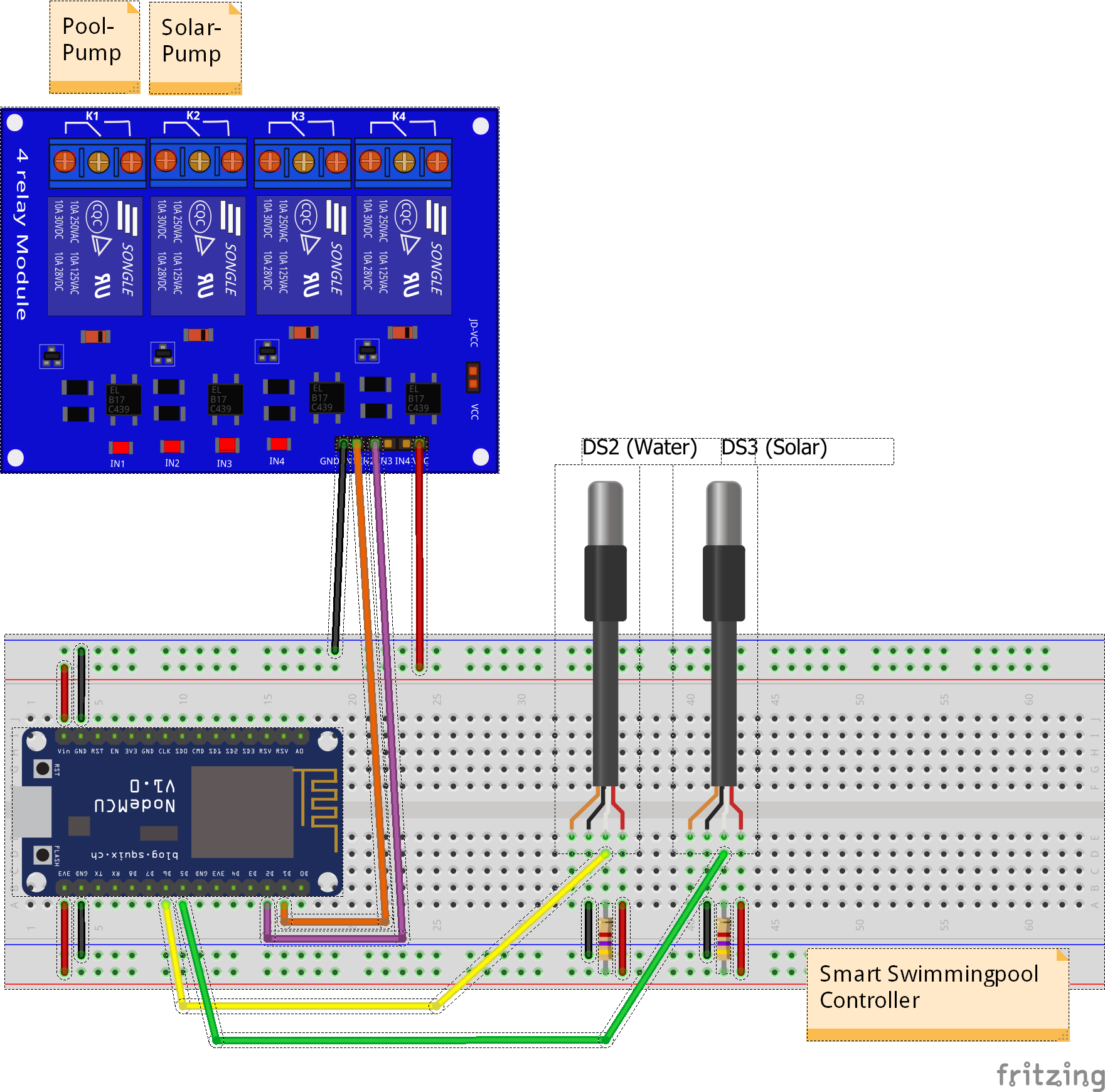
Pool Controller breadboard prototype
Example breadboard setup with ESP32, DS18B20 sensors, and relay module.
🧩 Option B: Permanent Assembly (Perfboard)
1️⃣ Plan Layout
- Arrange components on the perfboard before soldering.
- Keep 230V relay terminals at one edge, sensor connections at the opposite edge.
2️⃣ Solder Components
- Solder pin headers for the ESP32 (use a socket, don’t solder the ESP32 directly).
- Solder the 4.7kΩ resistors between DATA lines and 3.3V.
- Solder pin headers for the relay module (use a socket).
- Solder screw terminals for sensor/power connections.
3️⃣ Wire Routing
- Use solid core wire for connections.
- Keep data lines short and separate from power lines.
- Use different colors for clarity (e.g., red = power, black = GND, yellow = data).
4️⃣ Inspect Solder Joints
- Check each joint with a magnifying glass or multimeter.
- A good joint is shiny and concave. A bad joint is dull or cracked.
5️⃣ Mount in Enclosure
- Use M2.5/M3 nylon standoffs to mount the ESP32.
- Drill holes for sensor cables and relay wires.
- Use cable glands (PG7/PG9) for water-resistant sealing.
🔌 Connect 230V Load (Pumps)
⚠️ WARNING: 230V AC is dangerous! Proceed with caution.
- Disconnect mains power before wiring.
- Connect the pump’s live (L) wire to the relay’s COM (common) terminal.
- Connect the relay’s NO (normally open) terminal to the pump.
- Connect the pump’s neutral (N) wire to the neutral bar.
- Always use an RCD (FI circuit breaker) for the pump circuit.
L (mains) —— RCD —— MCB —— COM1 (Relay) —— NO1 —— Pool Pump
                          COM2 (Relay) —— NO2 —— Solar Pump
N (neutral) ─────────────────────────────── Neutral Bar —— Pump N
💻 Step 3: Flash Firmware
📥 PlatformIO (Recommended)
1️⃣ Install PlatformIO
- Install VS Code from https://code.visualstudio.com/.
- Install the PlatformIO extension in VS Code.
2️⃣ Download Firmware
Clone the repository:
git clone https://github.com/smart-swimmingpool/pool-controller.git
cd pool-controller
Open the
pool-controllerfolder in VS Code.
3️⃣ Upload Firmware for ESP32 DevKit
Connect the ESP32 to your computer via USB.
In PlatformIO, select the
esp32devenvironment.Run:
pio run -e esp32dev -t uploadWait for upload to complete.
4️⃣ Upload Web Interface Files (LittleFS)
Before configuring WiFi for the first time, upload the web assets:
pio run -e esp32dev -t uploadfsWait for LittleFS upload to complete.
🌐 Step 4: Configure WiFi & MQTT
📶 Initial WiFi Setup (AP Mode)
When the controller boots for the first time (or has no WiFi configured), it starts in Access Point (AP) mode:
- Power on the controller.
- On your phone/laptop, connect to the WiFi network:
- SSID:
Pool-Controller-Setup(open network, no password).
- SSID:
- Open a browser and go to:
http://192.168.4.1(the captive portal redirects automatically).
- Go to the WiFi Setup tab.
- Scan networks, select yours, and enter the password.
- Click Save – the controller will reboot and connect to your WiFi.
Note: In AP mode, the web interface has no password (intentional for setup). Once connected to your WiFi, a login is required (default password:
admin).
🔗 MQTT Configuration
Find the controller’s IP address on your network:
Check your router’s DHCP client list.
Or use
nmap:nmap -p 80 192.168.1.0/24 # Scan your subnet for open port 80
Open a browser and go to
http://<controller-ip>/.Log in with the default password:
admin.Go to the MQTT Settings tab.
Configure the following:
- MQTT Hostname/IP: Your MQTT broker address (e.g.,
192.168.1.100orlocalhostif running on the same device). - MQTT Port:
1883(default). - MQTT Username/Password: Optional (if your broker requires authentication).
- MQTT Hostname/IP: Your MQTT broker address (e.g.,
Click Save and reboot the controller.
🏠 MQTT Broker Setup (Optional)
If you don’t already have an MQTT broker, install Mosquitto on a Raspberry Pi or local server:
Install Mosquitto on Raspberry Pi
sudo apt-get update
sudo apt-get upgrade
sudo apt-get install mosquitto mosquitto-clients
Start Mosquitto
sudo systemctl start mosquitto
sudo systemctl enable mosquitto  # Auto-start on boot
Test MQTT Connection
# Subscribe to all topics (in one terminal)
mosquitto_sub -h localhost -t "#" -v

# Publish a test message (in another terminal)
mosquitto_pub -h localhost -t "test" -m "Hello MQTT!"
🏡 Step 5: Integrate with Smart Home
📱 Option A: Home Assistant (Recommended)
The Pool Controller automatically integrates with Home Assistant via MQTT Discovery (v3.3.0+).
1️⃣ Prerequisites
- Home Assistant installed (see https://www.home-assistant.io/).
- MQTT Broker configured in Home Assistant (see MQTT Integration).
2️⃣ Add MQTT Integration to Home Assistant
- Open Home Assistant.
- Go to Settings > Devices & Services > Add Integration.
- Search for MQTT and add it.
- Configure the MQTT broker settings (same as in Step 4).
3️⃣ Discover Devices
- After rebooting the Pool Controller, Home Assistant will automatically discover the device.
- Go to Settings > Devices & Services > MQTT to see the new device.
- All entities (sensors, switches, etc.) will appear under the Pool Controller device.
4️⃣ (Optional) Import Lovelace Dashboard
A ready-to-use Lovelace dashboard is available in the repository:
📱 Option B: openHAB
1️⃣ Prerequisites
- openHAB installed (see https://www.openhab.org/).
- MQTT Binding installed (via Paper UI > Add-ons > Bindings > MQTT Binding).
2️⃣ Configure MQTT Broker
Edit the MQTT configuration file:
sudo nano /etc/openhab2/services/mqtt.cfgAdd your broker settings:
mqtt:broker.url=tcp://localhost:1883
mqtt:broker.clientId=openhab
mqtt:broker.user=your_username
mqtt:broker.password=your_password
Restart openHAB:
sudo systemctl restart openhab2
3️⃣ Manually Add Devices
Since Homie support was removed in v3.3.0, you need to manually configure the MQTT topics in openHAB. See the openHAB Configuration Guide for examples.
🔍 Step 6: Test & Troubleshoot
✅ Verify Sensors
- Open the Web Dashboard (
http://<controller-ip>/). - Go to the Dashboard tab.
- Check the Solar Temperature and Pool Temperature values.
- If you see
-127°CorSensor error:- Verify the 4.7kΩ pull-up resistor is connected.
- Check VDD (3.3V) and GND connections.
- Ensure the DATA pin matches the firmware configuration (GPIO32/33).
- If you see
✅ Test Relays
- In the Web Dashboard, go to the Configuration tab.
- Set the Operation Mode to Manual.
- Turn on the Pool Pump and Solar Pump switches.
- The relay should click, and the pump should start.
- If the relay doesn’t click:
- Verify the relay module is powered (5V).
- Check the logic level (active-low expected).
- Ensure the relay switches when GPIO goes LOW (LED behavior may vary by module design).
✅ Check LED Status Codes
The built-in LED on the ESP32 indicates the system state:
| LED Pattern | System State | What to Do |
|---|---|---|
| Rapid blink (5 Hz) | AP Mode (no WiFi configured) | Connect to Pool-Controller-Setup and configure WiFi. |
| Slow blink (1 Hz) | WiFi connecting | Wait for connection (5–20 seconds). |
| Mostly on, brief blink every 2s | WiFi OK, MQTT disconnected | Check MQTT broker address/network. |
| Solid on | Fully connected (WiFi + MQTT) | Everything is working! |
| Very fast blink (10 Hz) | OTA Update in progress | Do not power off! |
| Double blink | Safe Mode (boot-loop detected) | Check serial log for errors. |
🐞 Common Issues & Fixes
| Problem | Cause | Solution |
|---|---|---|
| Sensor error (-127°C) | Missing pull-up resistor | Add 4.7kΩ between DATA and 3.3V. |
| Sensor error | Wrong GPIO pin | Check PIN_DS_SOLAR/PIN_DS_POOL in src/Config.hpp. |
| Relay doesn’t click | Wrong logic level | Use an active-low trigger relay module (firmware expects active-low signals). |
| Relay clicks but pump doesn’t run | 230V wiring issue | Check COM/NO terminals and pump connection. |
| ESP32 won’t boot (brownout) | Insufficient power | Use 5V/≥1A power supply. |
| ESP32 resets when relay switches | Voltage spike | Add flyback diode or use module with built-in protection. |
| Sensor readings jump when relay switches | Electrical noise | Route sensor wires away from relay/power wires. |
| MQTT connection fails | Wrong broker settings | Verify MQTT host/IP/port in Web UI. |
| Home Assistant doesn’t discover device | MQTT Discovery not working | Delete old retained messages and reboot controller. |
🎉 Step 7: Next Steps
📌 Recommended Next Steps
- Calibrate sensors (compare with a reference thermometer).
- Set up automation rules in Home Assistant/openHAB (e.g., “Turn on pump if temperature > 25°C”).
- Add Grafana dashboards for long-term data visualization (see Grafana Dashboard Guide).
- Explore advanced features (e.g., OTA updates, custom MQTT topics).
🔗 Useful Links
- Hardware Guide (detailed wiring diagrams)
- MQTT Configuration (advanced MQTT setup)
- Home Assistant Integration
- openHAB Configuration
- Grafana Dashboard
📝 Changelog
- 2026-06-16: Initial Quick Start Guide created (based on community feedback).
🤝 Contributing
Found an issue or have a suggestion? Open an issue or PR on GitHub:
📄 License
This guide is part of the Smart Swimming Pool project, licensed under the MIT License. See LICENSE for details.